Specialized in Civil Engineering Design and Temporary Earth Retaining System Urban Space Engineering Co., Ltd.
Home > HRW method > Overview of the Technology
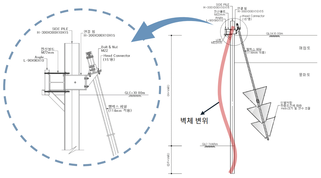
※ The above configuration may vary depending on site conditions.
| Equipment Name | Capacity | Quantity | Remarks | Special Notes |
|---|---|---|---|---|
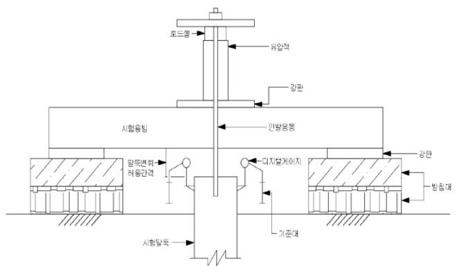
| Jack, Pump | 250Ton | 1set | Hydraulic | - |
| Road Cell | 500Ton | 1ea | - | Verification of Inspection and Calibration Certificate |
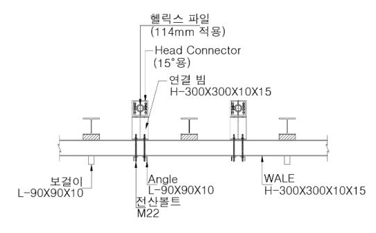
| Load-Bearing Platform | 150Ton | 1set | H-pile | H-300×300×11×18 |
| Reference Beam | 5.0m | 2ea | Steel | 100×100 |
| Digital Gauge | 50.0mm | 2ea | Anout 1/100mm | Verification of Inspection and Calibration Certificate |
| Magnetic Holder | - | 2ea | Magnetic Type | - |
| Other Auxiliary Equipment | - | 1set | Stopwatch, data Steel , etc. | - |
| Teat-1 [No.1] | Teat-2 [No.2] |
|---|---|
 |
 |
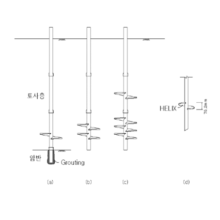
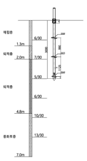
| Category | Test Location | Pile Type(mm) | Penetration Depth(m) | Number of Helices(ea) | Test Date | Type |
|---|---|---|---|---|---|---|
| Test-1 | No.1 | ø114.1(gt) | 3.0 | 1ea | 2023.06.01 | HELICAL PILE |
| Test-2 | No.2 | ø114.1(gt) | 3.0 | 3ea | 2023.06.01 | HELICAL PILE |
| Sectional View | |
|---|---|
| Teat-1 [No.1] | Teat-2 [No.2] |
 |
 |
| Teat-3 [No.3] | Teat-4 [No.4] |
|---|---|
 |
 |
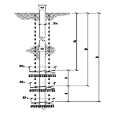
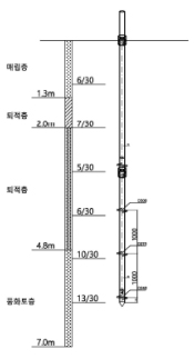
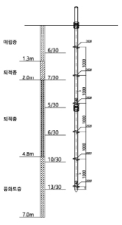
| Category | Test Location | Pile Type(mm) | Penetration Depth(m) | Number of Helices(ea) | Test Date | Type |
|---|---|---|---|---|---|---|
| Test-3 | No.3 | ø114.1(gt) | 3.0 | 3ea | 2023.06.01 | HELICAL PILE |
| Test-4 | No.4 | ø114.1(gt) | 3.0 | 6ea | 2023.06.01 | HELICAL PILE |
| Sectional View | |
|---|---|
| Teat-3 [No.3] | Teat-4 [No.4] |
 |
 |
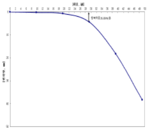
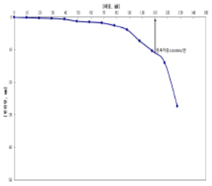
| Category | Test Location | Maximum Applied Load(kN/ea) | Pullout Amount(mm) | Residual Settlement(mm) |
|---|---|---|---|---|
| Test-1 | No.1 | 49.05 | 38.41 | - |
| Test-2 | No.2 | 65.67 | 46.75 | 43.94 |
| Test-3 | No.3 | 127.53 | 31.39 | - |
| Test-4 | No.4 | 264.57 | 57.89 | 55.97 |
※ "It has been shown that the number of helices and the cross-sectional areaat the same penetration depth affect the pullout resistance.
